So I thought about what to add first, but I figure the most useful thing is to contribute something that not many of us look at, but we probably should.
What happens when the lights go off at home? Not metaphorically – literally. When the power stops, does your network? Mine did.
So, I thought about getting a UPS (and I eventually did). Which is nice, but boring.
I live in Australia, so we use 240V AC as our mains. If you live in a country on a different voltage, just think your mains voltage when I say 240. Sorry, I didn’t feel like writing a script to do a geoIP search, and then look up the international voltage for that geographical location, and converting for you writing 240 is so much easier.
But I digress..
My modem, router, and NAS all use 12VDC. This meant that I was taking 240V mains, stepping it down for charging the UPS battery, and passing through to the “protected” output. When power stops, I was stepping up from the UPS battery to give me 240V “protected” out.
Now, once I get power from the UPS, I was then stepping back down to 12V DC for each of my devices.
?
Really? Is that the best way?
Now the overly observant of you may have noticed the “protected” was perhaps not completely accurate. Let me explain.
When most (cheaper, typically “Line-interactive”) UPS systems convert back to 240v, they use the cheapest method possible. this is often “Modified Sine Wave”. It’s not as clean a signal, and certainly not as friendly to your “protected” devices. Also, they don’t nearly isolate your equipment from spikes and surges as you may like. better than nothing, certainly, but far from ideal.
I’ve been introduced to “Double Conversion” or “Full-online” UPS’es. These essentially completely separate the conversion circuits on either side of the battery, forcing ALL of your voltage to go through the battery. This way, even if the input side stops supplying power, there is no reaction time for your output stage – it doesn’t “kick in” – it’s always there, supplying stable power. Yes, this means your battery is the most likely point of failure, but really – isn’t that what a piece of lead is for??
Additionally, these (typically more expensive) devices convert back up to 240v with a pure sine wave inverter. Much sexier (and just a little more expensive).
But back to my home setup. I’m charging a 12v DC Battery as my backup source, and delivering power to my devices, that need 12V DC.
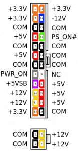
So why go back to mains? I decided not to bother. So instead, I got a cheap (and small) PC Power supply from eBay, capable of delivering to total 12V current required for all my devices + a reasonable increase for charging (I assumed +50% or more – I think mine can do 600%, but hey, there is enough power!). I bought an ultra-small form factor PC power supply, and modified it for 12V output only. Be warned. Warranties are voided, and potential shocks lurk inside a PSU case. Be careful. You’ve been warned. If you are worried, the simplest thing is to collect the 12v ground lines (some of the black wires) as your (-)’ve and the (yellow) +12v lines as your (+)’ve terminals. Cable tie all the others together somewhere they won’t touch anything (especially themselves).
The only trick is you need the bright green wire in the ATX connector shorted to one of the black ground wires. This means the “soft power on” operates, telling the power supply to turn on. If your PSU doesn’t have a hard-wired on/off switch, you could connect it here, so if shorted through the switch, the PSU comes on.
After you have your 240vAC >12v supply sorted, you have the ability to connect to your devices. However I introduced one additional crazy device.
Solar Panels are used to supply voltage during the day, and charge batteries. This way, you can use power from the solar cells when there is sunlight, and battery power when there isn’t (typically at night 🙂 but not always).
A device often used to control this is… a solar charge controller! Inventive namers aren’t they?
They’re also typically known as an MPPT. I bought one on eBay for a couple of dollars, so I could use it. Only trick – make sure it can handle both the voltage AND CURRENT of what you are doing. Include some tolerances just to be safe. Not that you want it pulling more than your typical – just make sure it isn’t going to melt!
Now all you need is to get some appropriate DC connectors for your devices, so you don’t need the manufacturer’s power pack. Wire that to some cables so you aren’t compressed into the same 5mm location for each device. Double check your polarity before you get to hook them all up. No really – check it! Residential gear doesn’t expect you to be mucking with the PSU!
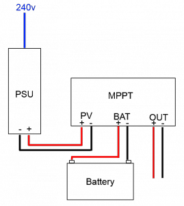
Follow your MPPT’s manufacturer’s instructions for exact hook-up procedure, but the general idea is:
- Connect the (switched off) 12V supply as the “solar cell”. Later, when you switch it on, if power to the mains is working, you will have power coming in (like when there is sun).
- Connect the battery as normal to the MPPT, avoiding short circuits.
- Connect your output connectors for each device (get your polarity right), and hook up to each device.
- Power on the PSU, and use the MPPT to allow power to charge batteries/drive your load (modems, etc.)!
Voila! 12v available all the time.
As for the UPS, it now cares for other devices in my network. That way, even when the lights go out, the rest doesn’t.
Cbailey


